English
 日本語
 Deutsch
 عربى
 中文


Solar Panel Mounting Bracket Selection: Interface, Coating, and Load Path
 2026.11.05
 Industry News
A 480 kW rooftop project rarely goes wrong because the modules arrived late. It goes wrong because someone bought standing-seam clamps for a 25 mm seam and the roof turned out to have a 32 mm profile, or because the rail coating was specified for an inland site while the building sits 900 m from the coast. Brackets are inexpensive next to modules and inverters, yet they carry every load the array will ever see and they are the hardest item to change once the modules are on the roof.
So here is the conclusion first: treat the solar panel mounting bracket as a load-path and corrosion decision, not a hardware purchase. Fix the interface, then the material and coating, then the price. What follows explains why that order matters and which checks actually prevent site delays.
What a Solar Panel Mounting Bracket Actually Carries
Every bracket does three jobs at once: it transfers the array's dead load into a structural member, it resists wind uplift and snow pressure, and it keeps dissimilar metals apart while letting water drain away. Get any one of those wrong and the symptom appears months later as a loosened clamp, a deflected rail, or white corrosion blooming around a bolt head.
The loads that surprise first-time buyers are rarely the obvious ones:
- Dead load: a 2278 × 1134 mm module weighs roughly 27–32 kg, so the module itself is not the problem. The accumulated weight of rails, clamps, cable trays and, on some roofs, ballast is.
- Wind uplift: pressure at corner and edge zones can be far higher than in the field of the array, which is why perimeter brackets and clamps are usually spaced more densely than interior ones.
- Thermal movement: aluminium expands about 23 × 10⁻⁶ per °C, so a 20 m rail run moves roughly 4–5 mm across a 10 °C swing. Slotted holes and expansion gaps are detailing requirements, not optional extras.
- Snow and maintenance loads: a technician standing on a rail plus 300 mm of wet snow is a legitimate design case.
The bracket also sits where two tolerance worlds collide: the module maker's clamping zone (commonly 300–400 mm in from the frame corner, with 30 mm or 35 mm frame heights) and the builder's roof or foundation, which is never exactly where the drawing says. Adjustability absorbs that gap, and on site it is worth more than a slightly lower unit price.
Match the Bracket to the Roof Interface
Roof brackets are selected by surface type, and the first question is whether you are permitted to penetrate the waterproofing at all. Trapezoidal metal roofs accept self-drilling screws with EPDM washers; standing-seam roofs take non-penetrating seam clamps whose load rating depends on the seam profile and the panel thickness; tile roofs use stainless hooks with the tile lifted and refitted over flashing; membrane roofs need welded pads or ballast; flat concrete roofs normally get non-penetrating ballast trays or chemically anchored pedestals.
Non-penetrating does not automatically mean safer. Ballast weight has to sit inside the roof's live-load allowance, and ballast alone rarely resists uplift unless it is combined with mechanical restraint or wind deflectors at the perimeter. On older concrete roofs the anchor pull-out test result, not the catalogue figure, decides the spacing.
Bracket selection tree: interface first, hardware second
Solar panel mounting bracket
Roof interface
Standing seam: non-penetrating seam clamp
Trapezoidal metal: screw-fixed rail with EPDM washer
Tile: stainless hook plus flashing
TPO / PVC membrane: welded pad or ballast
Flat concrete: ballast tray or anchored pedestal
Ground interface
Soil: driven pile or concrete pad
Rock and slope: single-column sleeve, double column
Water: fishery hybrid with service walkway
Sand: high-clearance wind-and-sand fixed array
Figure: the interface decides the bracket family; load and corrosion checks then set the section, coating and clamp.
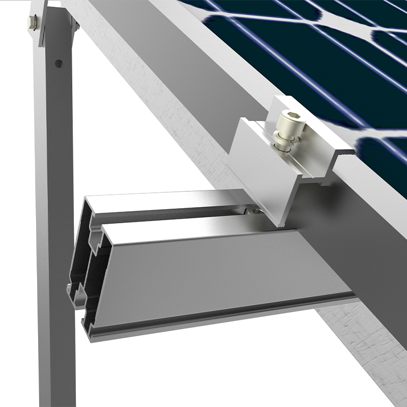 Non-Penetrating Flat Roof PV Mounting SystemCounterweight-based mounting for concrete flat roofs, with adjustable tilt and no roof penetrations, suited to commercial and public buildings.View Product →
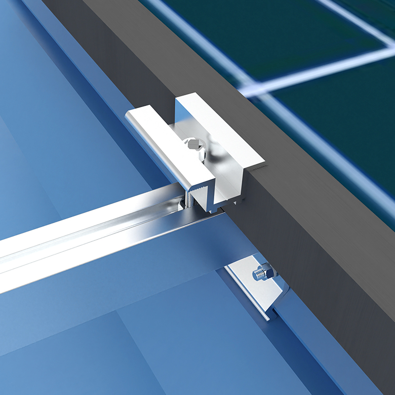 Metal Roof PV Mounting for Clamp-Type InstallationsNon-penetrating clamp system for color steel and galvanized metal roofs, supporting modular layout and tilt adjustment on industrial and warehouse buildings.View Product →
Two practical details close most roof cases. First, the clamp lip must match the frame height and the clamping zone the module maker marked; clamping outside that zone is a warranty argument waiting to happen. Second, roof-level cable routing and walkway loads belong in the same drawing as the brackets, because retrofitting them later usually means a second visit and a second mobilisation. Our roof PV mounting design and installation guide walks through the drawing set in more detail.
Ground and Rough Terrain: Where Tolerance Discipline Pays
On ground-mounted arrays the bracket stops protecting a membrane and starts surviving soil, slope and settlement. Driven piles are fast and cheap, but a pile driven 80 mm off grid pushes every downstream rail out with it; horizontal tolerances around ±50 mm and verticality within 1–2% are the sort of figures worth writing into the contract rather than discovering at commissioning.
Terrain is where standard products fail quietly. A cross-slope of 10–30° on a mountain site needs stepped or adjustable columns, and the choice between a single-column sleeve and a double-column frame usually comes down to ridge width, access for the drilling rig, and the bending moment the profile can take. Sandy sites add abrasion and burial: raising the lowest rail clear of drifting sand, avoiding open profiles that trap grit, and specifying fasteners that will still turn after a decade of dust. Water-mounted arrays combine humidity, changing water levels and maintenance access, so galvanizing thickness and walkway design matter more than rail stiffness.
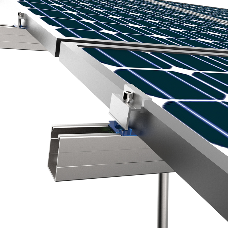 Double Column Ground PV Mounting SystemSymmetrical double-column ground mounting for mountainous or coastal high-wind and snow sites, with transverse connectors and embedded-pile or concrete-pier foundations.View Product →
Across agriculture, fishery, desert and mountain settings, the shared lesson is that ground PV mounting systems are specified around foundations and drainage first, and steel tonnage second.
Materials and Corrosion: The Decision That Outlasts the Price
A bracket is expected to last 25 years in the open, so the coating is not a cosmetic choice. Hot-dip galvanized carbon steel per ISO 1461 typically carries 55–85 µm of zinc and suits inland and industrial C3–C4 environments; aluminium 6005-T5 extrusion is lighter and cleaner on roofs but must be isolated from galvanized steel with EPDM or nylon washers to stop galvanic attack; stainless 304 is adequate for most inland work, while 316 is the minimum for chloride exposure near the coast or above water.
| Bracket material | Typical finish | Best-fit environment | What to verify at delivery |
|---|---|---|---|
| Carbon steel Q235B / Q355B | Hot-dip galvanized, 55–85 µm zinc | Ground arrays, carports, inland and industrial sites | Zinc thickness reading, drain holes present, no uncoated cut edges |
| Carbon steel with zinc-aluminium-magnesium coating | Coil-coated or mill finish | Cost-sensitive inland rooftops | Cut-edge protection and coating adhesion report |
| Aluminium 6005-T5 | Anodized or mill finish | Rooftop rails, low-load roofs | Alloy and temper certificate, isolation washers supplied |
| Stainless steel 304 / 316 | Passivated | Tile hooks, coastal and water-mounted arrays | Grade marking on the part, salt-spray test report |
Two procurement habits separate a clean project from a recurring one. Ask for the zinc thickness as a measured value rather than a specification, and confirm that bolts are at least grade 8.8 with the torque value printed on the packing list, because an installer who has to guess torque will either under-tighten or shear the bolt.
Purchasing Checklist: What to Lock Down Before the Order
Most bracket disputes trace back to information that was never exchanged, not to a defective part. Before the purchase order goes out, settle these six points:
- Design basis: wind pressure, snow load, seismic category and the design life, plus a named party responsible for the load calculation.
- Interface survey: seam profile and thickness, tile type, membrane material, roof structure, soil report or rock condition, photographed and dimensioned.
- Coating class matched to corrosivity, with the inland or coastal distinction written into the specification.
- Module compatibility: frame height of 30 mm or 35 mm, clamping zone, and mid-clamp versus end-clamp layout.
- Adjustability and tolerances: slot lengths, column adjustment range, and the pile or anchor tolerance you will accept.
- Documentation: test reports, torque values, batch traceability, and packing lists organised per array so site teams are not sorting mixed crates.
Warranty deserves the same attention. A stated 25-year design life with a warranty shorter than the project's financing term shifts the corrosion risk back onto the owner, and that gap is far more expensive than any bracket price difference.
The bracket is the smallest structural item on the drawing and the one that decides whether the array survives its twentieth winter. Choose the interface first, match the coating to the exposure, and put tolerances and documentation in writing before the container ships. Do that and price becomes a comparison between equals, not a gamble on which supplier will still answer the phone in year five.
Message Us Now !

 +86-0523-80509588

 11th Floor, Wenchuang Building, 60 Fenghuang East Road, Hailing District, Taizhou City, JiangSu, China
Mounting Systems
Copyright © Taizhou Suneast New Energy Technology Co., Ltd.
All Rights Reserved.
 OEM/ODM Solar Panel Mounting Bracket Manufacturers