English
 日本語
日本語 Deutsch
 عربى
عربى 中文
中文
Is the carport PV mounting system compatible with different sizes and types of photovoltaic modules?
 Industry News
The Fundamental Design of Carport PV Structures
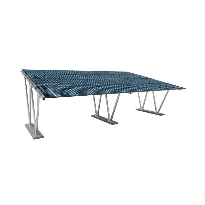
A carport PV mounting system is fundamentally a dual-purpose structure engineered to provide shelter for vehicles while simultaneously serving as a platform for photovoltaic modules. Unlike a traditional ground-mount or roof-mount system, the carport structure must first and foremost meet structural engineering requirements to ensure safety and durability. It must withstand loads such as wind, snow, and the weight of the modules themselves. The primary components typically include steel or aluminum columns that support a roofing structure, which is then fitted with the mounting hardware for the solar panels. The design of this roofing structure is where compatibility begins. It is not merely a flat surface but is engineered with a specific framing layout, often consisting of purlins or rails running across the top of the main beams. The spacing, dimensions, and material of these structural members are foundational to determining which photovoltaic modules can be accommodated. The system must integrate the structural needs of a carport with the precise alignment requirements of a solar array, creating a framework that is both robust and adaptable.
Accommodating Variations in Module Dimensions
Photovoltaic modules come in a wide array of sizes, with variations in length, width, and thickness. A well-designed carport solar structure must be able to handle this dimensional diversity. The primary mechanism for this adaptability lies in the mounting rails or purlins that form the base for the modules. These rails are typically installed with adjustable fixing points or are designed to be positioned at variable intervals. This allows the installers to match the mounting points to the pre-drilled holes on the frame of the photovoltaic module, regardless of whether it is a standard 60-cell, 72-cell, or one of the newer large-format panels. The length of the carport bays—the sections between supporting columns—also plays a role. A system with longer bay spans can more easily accommodate longer modules without requiring additional structural supports. For the width, the system's transverse members must be spaced correctly to support the module along its shorter edge. Furthermore, the clamping mechanisms used to secure the modules to the rails often have a range of adjustment. These clamps are designed to grip the module frame, and their design must account for different frame thicknesses, ensuring a secure connection without damaging the module. This adjustability in the mounting hardware is crucial for accommodating the variety of module frames available from different manufacturers.
Compatibility with Different Module Technologies
Beyond physical dimensions, different photovoltaic module technologies present unique considerations for a mounting system. The most common type is the glass-film crystalline silicon module, which has a rigid aluminum frame. These are generally straightforward to mount with standard clamping systems. However, other technologies exist. Glass-glass modules, which have solar cells encapsulated between two layers of glass, often lack a conventional aluminum frame or have a very thin one. Mounting these modules requires specialized clamping systems that provide secure support over a larger surface area to distribute pressure evenly and prevent stress on the glass. Bifacial modules, which can generate electricity from both sides, also demand a specific mounting approach. To be effective, the rear side of a bifacial module needs to be exposed to light. A carport PV mounting system for bifacial panels must be designed to minimize shading on the back of the module. This often means using a more open-structured racking system with narrower rails and components placed further away from the active surface of the panel. The spacing between rows of modules also becomes more critical to avoid self-shading. The mounting system must therefore be flexible enough to implement these different installation strategies to suit the specific technology being deployed.
| Module Type | Primary Structural Feature | Mounting System Requirement |
|---|---|---|
| Standard Framed (Glass-Film) | Rigid aluminum frame on all sides | Standard end and mid clamps compatible with frame thickness |
| Frameless (Glass-Glass) | No frame or a minimal perimeter frame | Specialized clamps with a wider grip area to secure the glass edge |
| Bifacial | Active surface on front and rear | Minimal shading from racking components; increased module spacing |
| Module Size | Typical Dimensional Range | Mounting System Requirement |
| Standard | ~1m x 1.6m to 1m x 2m | Standard rail spacing and clamp placement |
| Large-Format | ~1.3m x 2.4m or larger | Wider structural bay spans; clamps rated for higher wind loads |
The Importance of Adjustable Mounting Hardware
The ability of a carport system to be compatible with various modules is heavily reliant on the adjustability of its hardware. The core of this is the module clamp. These are typically available in two types: end clamps, used for the outermost modules in a row, and mid clamps, used to join two adjacent modules. High-quality clamps are designed with a degree of vertical and horizontal adjustability. This allows for fine-tuning during installation to accommodate minor inconsistencies in module dimensions or to ensure a perfectly aligned array. The base of the clamp, which connects to the rail, often features a sliding mechanism or a series of slots, allowing the clamp's position to be adjusted along the length of the rail. This is essential for aligning the clamp with the module's mounting hole. The bolt that tightens the clamp is also a key component; it must provide sufficient clamping force to secure the module against wind uplift without being over-torqued, which could crack the module's frame or glass. Some systems incorporate torque-limiting features to prevent this. The material of the hardware, typically aluminum or stainless steel, must also be chosen to prevent galvanic corrosion when in contact with the module frame and the mounting rails, ensuring a long-lasting connection.
Structural Load Considerations for Different Modules
While a mounting system may physically accommodate a range of modules, it must also be structurally sound for each type. Different modules have different weights. A standard 60-cell crystalline module might weigh around 18-20 kg, while a large-format glass-glass module could weigh over 30 kg. When designing a carport solar installation, the total weight of the modules, combined with the weight of the mounting system itself, is a constant dead load that the structure must support. The mounting system manufacturer typically provides load charts that specify the maximum allowable module weight and the maximum permissible span between support points for the rails. For heavier modules, the spacing between the rails or the supporting purlins may need to be reduced to prevent the modules from bending or sagging, which could induce stress and lead to micro-cracks in the solar cells. Furthermore, the wind load calculations are affected by the module's size and shape. Larger panels present a greater surface area for wind pressure, which translates into higher uplift forces on the clamps and greater shear forces on the structural members. Therefore, the compatibility of a system is not just about fitting the module but also about ensuring the entire structure, from the clamp to the column foundation, is engineered to handle the specific static and dynamic loads imposed by that module.
Flexibility in System Layout and Orientation
The compatibility of a carport mounting system also extends to its flexibility in layout, which can influence module choice. Carports can be designed in various configurations, such as single-slope, dual-slope (gable), or even cantilevered designs. The orientation of the modules—typically facing south in the northern hemisphere—is fixed by the carport's orientation. However, the tilt angle of the modules is a design parameter. A system that offers a range of tilt angles provides more flexibility to optimize energy production based on the local latitude. This adjustability in tilt must be compatible with the length of the modules; longer modules may require more robust support at steeper angles to prevent excessive deflection. The spacing between rows of carports is another layout consideration. To avoid shading, especially when using taller modules or modules mounted at a steeper tilt, the spacing between the bays must be carefully calculated. A modular carport system that allows for variable bay widths and column placements provides the designer with the tools needed to create an optimal layout for the chosen module, ensuring that compatibility is maintained at the array level, not just at the individual panel level.
Manufacturer Specifications and Engineering Support
Ultimately, confirming the compatibility of a specific photovoltaic module with a particular carport PV mounting system comes down to consulting the manufacturer's documentation and engineering resources. Reputable mounting system providers produce detailed datasheets and installation manuals that list the compatible module types and sizes. These documents specify the acceptable range of module dimensions (length, width, frame thickness) and provide load capacity charts. They also offer guidance on installation best practices, including clamp placement, torque values, and required rail spacing for different scenarios. For projects that fall outside the standard parameters—such as using an unusually heavy or large-format module—manufacturers often provide engineering support. This can involve performing custom structural calculations to validate the design or suggesting modifications to the standard system. Relying on this manufacturer-provided data is a critical step in the design process to ensure that the final installation is safe, compliant with building codes, and will perform as expected over its operational lifetime. The system's compatibility is therefore a combination of its inherent design flexibility and the supporting technical information provided by its supplier.
Message Us Now !
 +86-523-80509588

 11th Floor, Wenchuang Building, 60 Fenghuang East Road, Hailing District, Taizhou City, JiangSu, China
Mounting Systems
Copyright © Taizhou Dongsheng New Energy Technology Co., Ltd.
All Rights Reserved.
 OEM/ODM Solar Panel Mounting Bracket Manufacturers